Step by Step Temperature Build Using the STC/ITC-1000
The STC-1000 is versatile digital temperature controller. It’s manufactured by a number of manufacturers
Specifications can very but you can generally speaking these are dual stage temperature controllers that you can use to help control temperature of your kegerator, fermentation chamber or as part of your brew system. Dual Stage means this can control a heating and cooling device. Alternatively, it can control a heating or a cooling device. Note that these are unwired controllers and will require some work to implement in your project.
STC-1000 vs ITC-1000
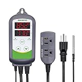
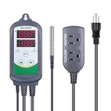
The STC-1000 is a great controller, arguably the best value in temperature controllers, especially if you’re on the handy side. The ITC-1000 from Inkbird is what I would call and upgrade to the STC-1000. The big upgrade is that the ITC-1000 display ins deg F and deg C, where most versions of the STC-1000 were deg C display only. Beyond there, it’s my understanding that there are some usability improvements in the ITC-1000.
If you’re looking for a pre-wired temp controller, consider – ITC-308 – Review
Some things to consider when buying an STC/ITC 1000 controller
- Input voltage. These can be powered by DC and AC 120 to 240
- Readout capabilities. Many STC-1000 controllers read in Celsius only. Some have the ability to read in Celsius or Fahrenheit.


The American Homebrewers Association has a great write up on a step by step build out of an STC-1000/ITC-1000 Temperature Controller Build. It includes a parts list, pictures and diagrams along with a step by step how to for getting this going.
How to Build a Temperature Controller for the AHA
by Duncan Bryant
This dual-stage temperature controller is perfect for managing temperatures of your kegerator, fermentation chamber or keezer. It allows for a hot and a cool trigger to be individually controlled, so you could have your fermentation refrigerator hooked up to the cold trigger and a heat source to the hot trigger. If the temperature falls below the target value, the heating device will be turned on, and vice versa.
Note: this project deals with electrical current and DIY’ers should pursue the build at their own discretion. Read through the directions entirely to have a full understanding of the build before diving in. If you are unsure of your abilities, consult with someone well versed in electrical wiring.
Make sure the components you use are compatible and rated for your intended application. Contact manufacturer with questions about suitability or a specific application. Always read and follow manufacturer directions.
The Build
Materials
Shop around for the best deals. I managed to get everything listed below for under $45. For this project, you’ll need to following materials:
This article contains affiliate links. We may make a small percentage if you use our links to make a purchase. You won’t pay more and you’ll be supporting Homebrew Finds and more content like this. Thank you for your support!
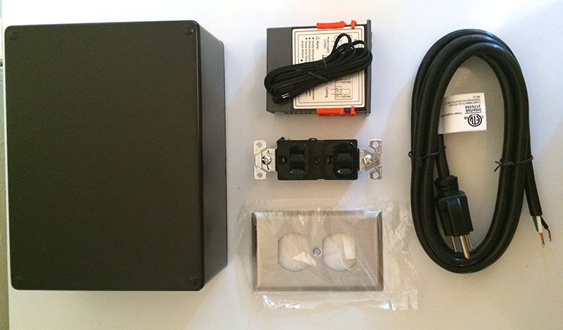
- STC-1000 Digital temperature controller with sensor (110v): This can be purchased from Amazon for around $18. Find a friend with Amazon Prime for free shipping!
- Project box: This will house the components and wiring of the project. I purchased a large, plastic project box from Radio Shack for $10, but any container that can safely hold electrical components will work.
- Power Outlet: One three-pronged, dual wall outlet. Don’t forget the wall plate!
- 8+ feet grounded power Cord: A three-pronged power cord is needed to supply power and provide the wires needed for the project. If you have an old extension cord, chop it up for this project. If not, I recommend purchasing a cord from a hardware store that comes with bare wires on one end. You will end up cutting out segments of this cord to strip to use the internal wires for this project, so make sure you get a long enough cable.
- Wire connectors: These are plastic, cone-shaped devices used to safely join wires together.
- Electrical tape: Tape is needed in conjunction with wire connectors to join wires


Tools
The following tools will make for the quickest and easiest build, though all are not necessarily required. Try borrowing from friends and family to keep the cost down!
- Screwdrivers: You will likely need a few different sized screwdrivers, including one fairly small flat-head for manipulating the STC-1000 inputs, and a philips head for the outlet connects.
- Wire strippers: Wire strippers will take a lot of work out of the harvesting of wires. If you don’t have a pair, carefully use scissors to remove plastic covering from wires.
- Needle-nose pliers: These are used to break the tab on one side of the wall outlet.
- Voltage meter or multimeter: This is a tool used to safely test wall outlets. Not necessary, but highly recommended.
- Dremel: The project box needs to have slots cut to hold the STC-1000 and outlet. A dremel fitted with a cutting bit will make a quick job of the process. If you don’t have a dremel, an X-Acto knife can be used. Be sure to buy a few blades, since they will likely break or dull during the process.

Preparation
Before jumping into the construction, take time to do some prep that will help speed up the overall process.
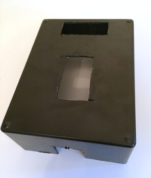
- Unpackage the project box, STC-1000 and wall outlet. Place the STC-1000 and power outlet where you want them on the box and trace with a pencil. Cut along the outline with the dremel. It may take a few rounds to get the fit just right. Test to make sure the STC-1000 (remove the orange tabs, they will be used later) and wall outlet fit snuggly into the holes cut in the project box. You will also want to cut a hole for the power cable and temperature probe to run out, and the location will depend on how you plan to mount the temperature controller. I cut mine at the bottom side of the project box so the wires would be aiming down when the temperature controller is mounted to the wall.
- Prepare the wires. For this build you will need eight 5-inch pieces of wire. Cut off a piece of
 the power cord and strip to reveal the internal wires. To keep things from getting too confusing, plan to cut three pieces of black wire, four pieces of white wire and one piece of green wire. The green wire is used for grounding and is not supposed to be used for anything other than the ground, so we recommend you do not use these for any of the hardwiring besides tying the outlet’s ground to the power cord’s ground. On either end of the wire segments, strip a half-inch of the insulation to reveal the inner wires.
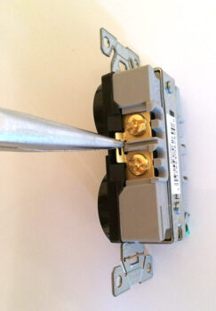
 - Break the bridge on one side of the power outlet to allow separate control of heating and cooling. If looking at the outlet from the front, this would be on the right side with only two screws, not the side with three screws. To break the tab, take a pair of pliers, grab the tab connecting the metal pieces beneath each screw, and bend back and forth until it snaps. It takes a bit of force.

Wiring
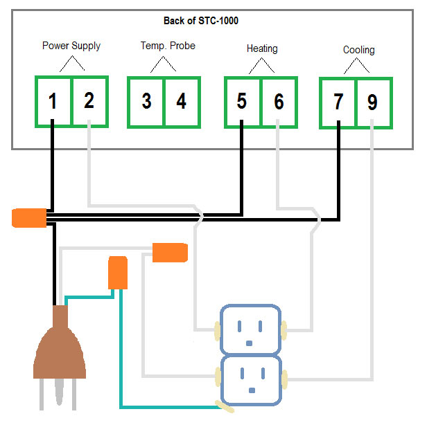
Follow the directions below carefully and reference the wiring diagram. If you have never wired anything before, seek a friend experienced in working with electrical current. It is also important to point out the the wiring process must be done as if the box is already constructed. If you do the entire wiring of the components outside the box, you wont be able to run the cords. The directions are intended to make this as little as an inconvenience as possible.
- In the 1, 5 and 7 slots of the STC-1000, secure a piece of black wire.
- In the 2, 6 and 9 slots of the STC-1000, secure a piece of white wire. Somehow mark the wire going into slot 6 as “hot” and the wire going into slot 9 as “cold”. This will prevent confusion later on.
- In the 3 and 4 slots of the STC-1000, secure the temperature probe, which comes with the STC-1000.
- Slide the STC-1000 into the project box until secure.
- IMPORTANT: All wires that will be connected to the power outlet should be run through the back of the hole for the outlet, but don’t mount the outlet at this point since you will need access to the screws on the side.
- Take all the black wires coming from the STC-1000 and the black wire coming from the power cord and twist the exposed wires together and cap with a wire connector. Use electrical tape to wrap the wire connector securely.
- Take the white wire coming from slot 2 and secure to the power outlet at the top screw on the side in which the tab WASN’T broken. This will be the side that has three screws. (Remember to run these wires through the hole that the outlet will be mounted).
- Take the white wire coming from slot 6 that you labeled “hot” and connect to the outlet at the top screw of the side with the broken bridge. This is the side that only has two screws. This means the top outlet will control whatever device you will use for heating.
- Take the white wire coming from slot 9 that you labeled “cool” and connect to the outlet at the bottom screw of the side with the broken bridge. This is the side that only has two screws. This means the bottom outlet will control whatever device you use for cooling.
- Connect a piece of white wire to the middle screw of the side of the outlet with three screws. Using a wire connector and electrical tape, connect this wire with the white wire coming from the power cord.
- Connect a green piece of wire to the bottom screw of the side of the outlet with three screws. Using a wire connector and electrical tape, connecting this wire with the green wire coming from the power cord.


Final Touches
You are almost ready to test your DIY temperature controller!
- With the STC-1000 in place, slide the orange clips back onto the STC-1000 to hold it securely to the project box.
- Mount the wall outlet to the project box with screws. It may be easiest to start the holes with a drill.
- Run the power cord and temperature probe through the hole you cut for this purpose. I recommend using a piece of electrical tape to secure the power cord and probe to the inside of the project box so if they get pulled on by accident, it won’t directly pull on the connections to the STC-1000.
- Place the back cover on the project box and screw closed.
- You can also add some sort of device to the back of the project box to mount it where you please. For now, I put magnets on mine and it hangs on the side of my keezer.

Testing
Before putting the temperature controller to work, take a moment to test that the device is working and triggering the outlets appropriately. For this, you will need the voltage reader mentioned under the tools above.
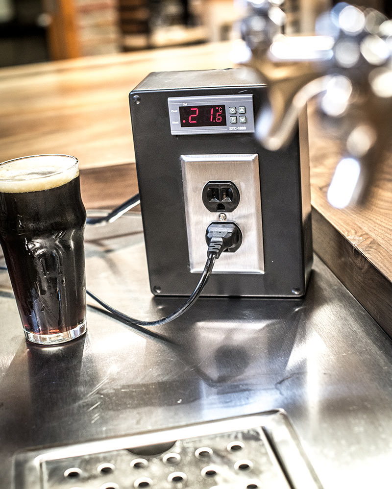
- Plug the completed temperature controller into the wall. The STC-1000 should power on immediately and show the current temperature the probe is picking up.
- Hold the up arrow on the STC-1000 to see what the current temperature is set at.
- On the left side of the STC-1000 you will see the labels “Cool” and “Heat”. When a red dot appears next to one or the other, this means the corresponding outlet should be issuing power (remember the directions above wired the cold trigger to the bottom and the hot to the top). Let’s assume there is a red dot next to heat.
- Take the voltage reader and test the top outlet. If the light comes on the voltage reader, all is good.
- Next, change the temperature so that the cool function will be triggered. To do this, hold the “S” button until “F1” shows up, then release. Then, while holding the “S” button, use the down arrows to set the temperature below the current ambient temperature. Once you’ve found a temperature you want, push the power button to accept. Now there should be a red dot next to the “Cool” label.
- Again, use the voltage reader and test the bottom outlet. If the light comes on the voltage reader, everything is working!
- If the STC-1000 doesn’t power on, or the voltage reader doesn’t light up when testing the appropriate outlet, open up the project box and make sure the wiring is correct and all the wire connectors are effective.
How to Use
Using this temperature controller is fairly easy. The overarching functionality is that a cooling device will be triggered when temperatures exceed the target value and a heating device will be triggered when temperatures drop below the target value.
We will walk through a few of the basics, but also plan to take the time to read the full STC-1000 manual for complete instructions.
On/off: When the temperature controller is plugged in, it will automatically power on. The number displayed is the current ambient temperature in Celsius being read by the temperature probe. To shut off, hold the power button until the display turns black.
Checking parameters: To see what the ambient temperature the controller is currently set to maintain, push the up arrow. Push the down arrow to see the “Difference Value”, explained below.
Editing parameters: The STC-1000 has four programmable parameters, explained below. To access these, hold the “S” button until “F1” appears in the display and then release the button. Use the up/down arrows to cycle through F1, F2, F3 and F4. To edit one of the parameters, cycle to the menu item in question, hold the “S” button and use the up/down arrows to change the value. Once the value you want is selected, push the power button to save.
Parameters Explained:
- F1 – temperature set value: This is the temperature that the controller is set to maintain.
- F2 – difference set value: This value determines the degree of allowable variation in Celsius before the controller kicks in. For example, if the F1 is set at 20°C with a F2 value of 0.3°C, the controller won’t kick in until the temperature raises to 20.3°C or drops to 19.7°C.
- F3 – compressor delay time: This value is in minutes and determines how long the controller will wait before kicking in when the temperature exceeds the difference set value.
- F4 – temperature calibration value: This can be used to calibrate the controller when inaccuracies occur.
via the AHA: How to Build a Temperature Controller
Make sure the components you use are compatible and rated for your intended application. Contact manufacturer with questions about suitability or a specific application. Always read and follow manufacturer directions.
Related:
- AHA Membership Deals
- Inkbird ITC-1000
- Inkbird Itc-308 – Review
- Yeast Starters & Fermentation
- Kegerator Tips & Gear
- Inkbird Temperature Controller Deals and Reviews!
About the American Homebrewers Association (AHA): The AHA is the voice of homebrewers in the United States. Membership in the AHA gets you Zymurgy Magazine along with pub and retail discounts, early access to event tickets, members only events and a lot more. If you’re not a member of the American Homebrewer’s Association.
This post may contain affiliate links. We may make a commission when you use our links. This will never cost you extra. Thank you for supporting Homebrew Finds!
Inkbird ITC-308 Digital Temperature Controller| Review


Make sure the components you use are compatible and rated for your intended application. Contact manufacturer with questions about suitability or a specific application. Always read and follow manufacturer directions. tag:lnksfxd top:stcitc100build tag:tpr